Showa bluesor how to fix your Monster / ST / etc. front spring holders (part 2).
Please go back to part 1 for the previous steps.
Step 7: Cartridge re-assembly into the fork.
Put the cartridge back into the fork (with the bottom locating washer / cartridge seat in place),
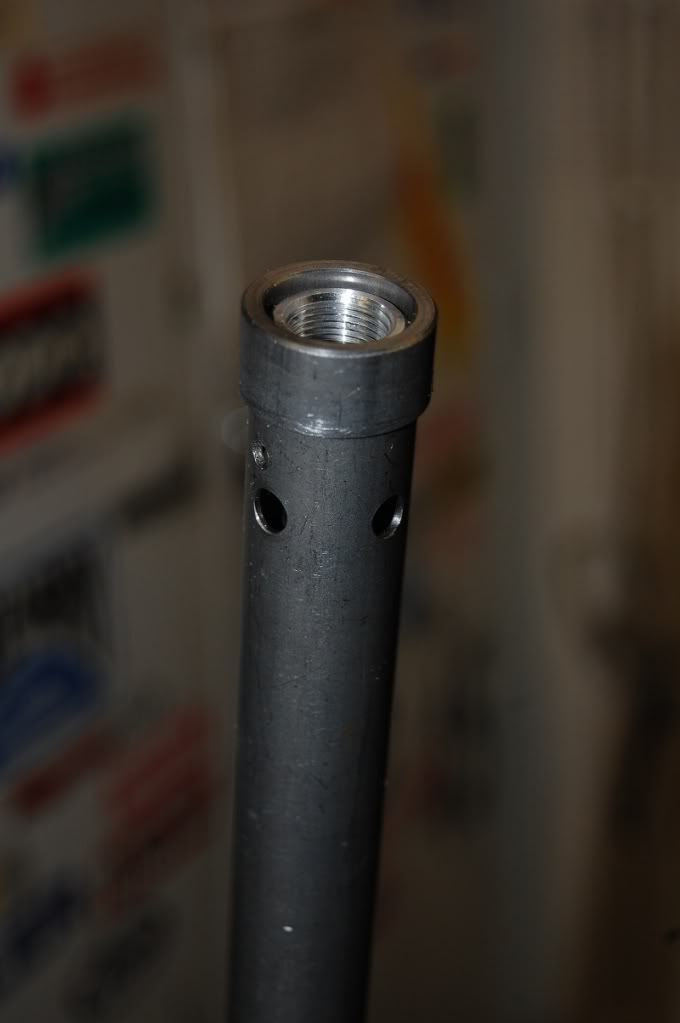
Fig. 7a:
Don´t forget to put the cartridge seat back on top of the cartridge before assembly in the fork.
put a new copper seal ring on the bottom screw, put some thread lubricating compound on the thread (do NOT use LocTite, or you´ll never be able to disassemble this again), and tighten in a few steps to 35 Nm.
Step 8: Rebound adjuster modification.
This is an optional extra, but it is probably a more robust solution to machine the rebound "needle" off the brass adjuster screw in the top nut. I have done some with the needle left, and some with the needle machined off, don´t really know if it matters.
I´ve also seen a few different "needle" designs, so if you machne the tip off, the removed length might be a bit different depending on what needle you happen to have.
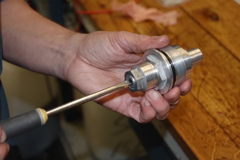
Fig. 8a:
To machine the adjuster, you obviously have to remove it from the top nut; just screw it out until it comes out.
After a while (about 35 clicks from full out) you will run out of clicks; just go on until you can push the needle out.Sometimes, the little spring-backed ball responsible for the clicks will drop out, but surprisingly often it stays put.
If it does drop out, peek into the top nut from the bottom. Just above the last thread you´ll see a small hole. Put a dab of grease on a small screwdriver to hold the ball and carefully put it back in the small bore.
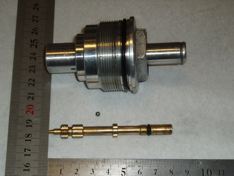
Fig. 8b:
Top nut (with spring pre-loader removed), "click" ball, adjuster screw with needle.
If you´d happen to lose the ball, don´t worry; you can get new ones at your bearing store. For some reason Showa has decided to use inch-sized balls, the ones I´ve checked were 1/8". If you do need them, buy something else at the same time; they are embarassingly cheap.
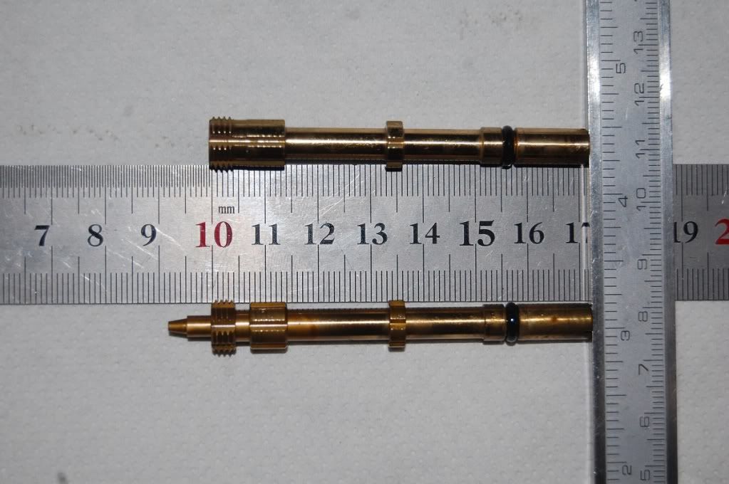
Fig. 8c:
Standard and machined adjuster screw. The tip is 8 mm long on this one.
Step 9: Rebound damping adjuster rod.
When you use a K-tech kit you do not need to manufacture any needles; you use the stock compression needle in the bottom plug, and the rebound needle comes with the kit. However, you have to manufacture an aluminium rod to control the rebound needle. To do this you must establish the proper length of this rod. Since the working space of the needle return spring is about 3 mm, you have to get this reasonably right, or you´ll miss the working range of the adjustment.
Take the needle with the spring, and drop it down the cartridge rod.
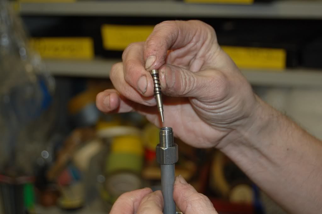
Fig. 9a:
This kit comes with this needle (no O-ring); it will drop right down the rod (or out of .... ).
Others I´ve seen come with an O-ring on the needle, this means you have to push the needle down the rod until it bottoms out.
Next, take a 5 mm diameter aluminium rod and push it down the tube and make a mark on the alu rod at the top of the cartridge rod. You want this to be to the closed position of the needle, so slightly press on the rod against the return spring of the needle until you can fell the needle stop against the seat.
Then, pull it out and measure the length.
Then take the fork top nut, back the adjuster screw all the way OUT, then screw it in again,counting the clicks until you run out of clicks; screw it back a little until you have distinct clicks again and note how many clicks you have.
You might have to do this a couple of times in order to make sure you´ve got it right. You will probably end up at around 35, and I usually set it at 25-26 clicks.
Measure the distance from the bottom surface of the top nut up to the tip of the brass adjuster screw, this distance beeing "a".
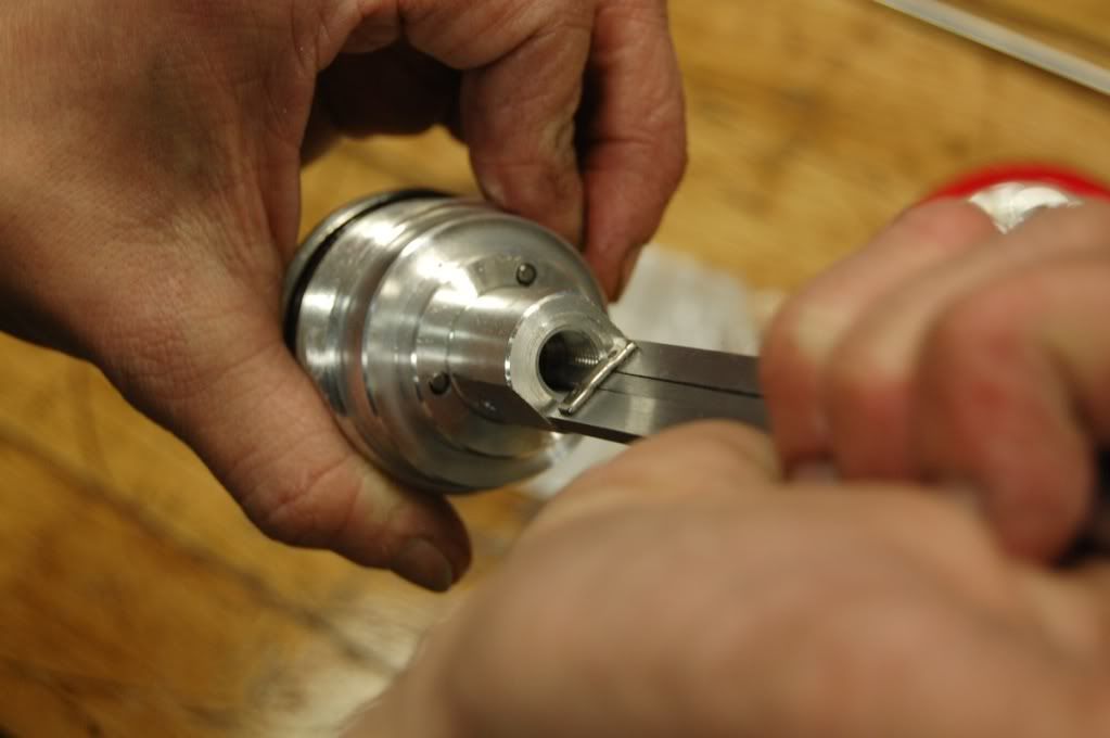
Fig. 9b:
Measure the distance to the adjuster needle in top nut; this is the distance "a".
Next, measure the lenght of cartridge rod above the lock nut, distance "b".
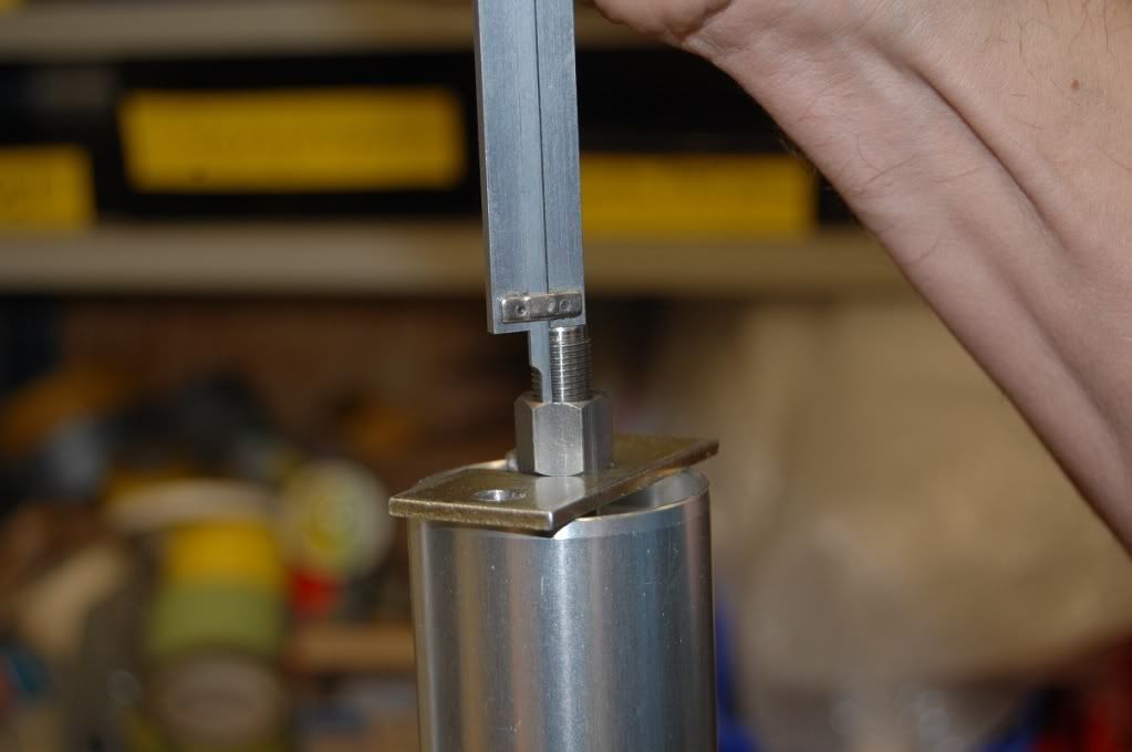
Fig. 9c:
Measure the part of the rod above the lock nut; this is the distance "b".
By deducting "b" from "a" you´ll get the amount of control rod that shall protrude above the cartridge rod end in order to get a working rebound adjuster.
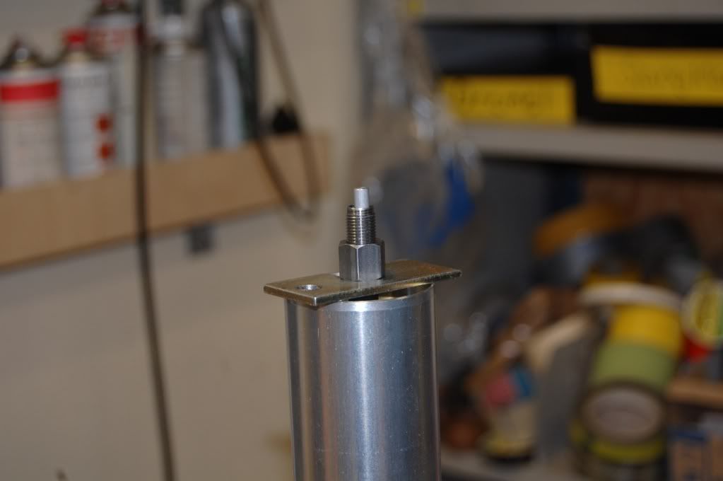
Fig. 9d:
This is about what it will look like if you have machined off the needle tip of the adjuster screw.
Edit 2013-01-25The current .... SHO13 kit has a longer rebound needle than the one you see in the picture above:
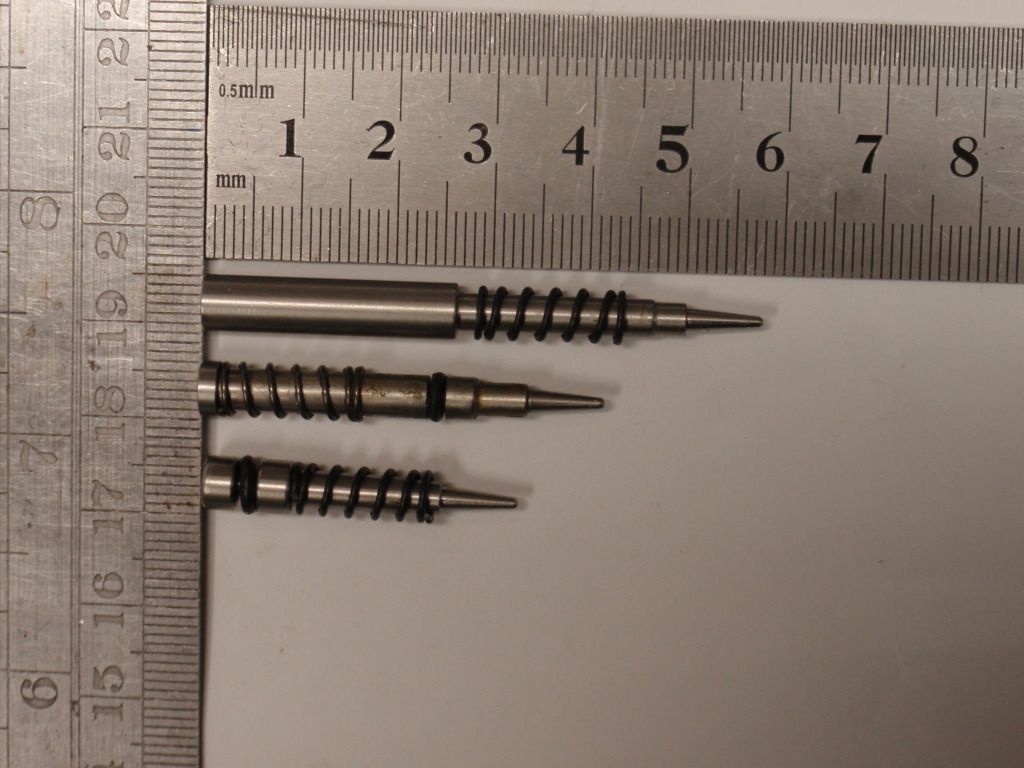
Fig.9d: Some different K-Tech rebound needles. The current ...SHO13 kit needle is the one on top.
With the ... SHO13 kit needle, the adjuster rod will look like this (picture 9d1 and 9d2):
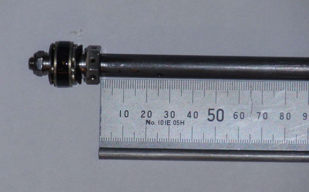
Fig. 9d1:
If you put the cartridge rod and adjuster rod along each other like this........
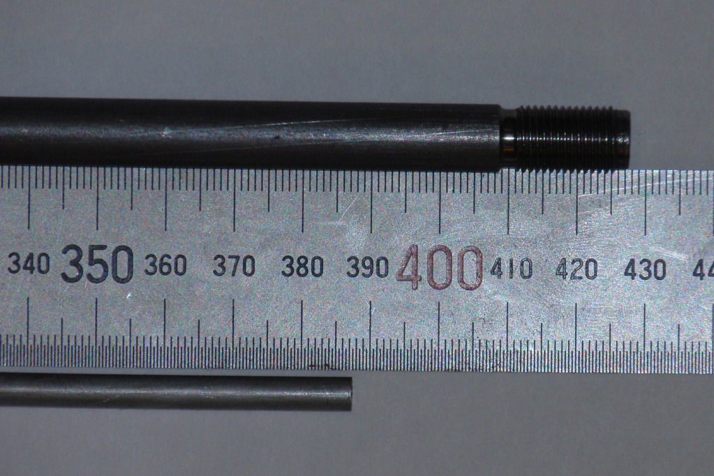
Fig. 9d2:
..... the adjuster rod should be appr. 41 mm shorter than the cartrige rod (still woth the brass needle tip machined off)
End edit 2013-1-25Edit 2013-02-27:
Also, I´ve added an O-ring on the control rod:
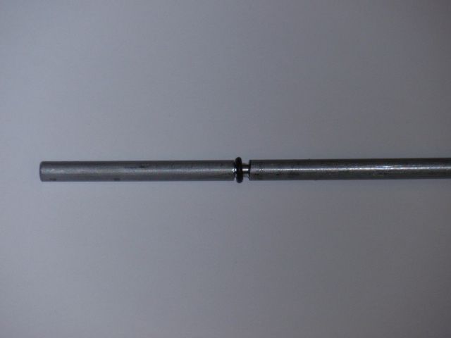
Edit: O-ring 6x4x1 mm, groove dia 4.2 mm.
The groove is square in profile, to keep the O-ring in.
End Edit.
Leave the needle tip and the control rod will be roughly flush with the cartridge rod.
You should do this pretty carefully so that you get close; minor adjustments can be done by screwing the lock nut up or down slightly on the cartridge rod.
To test if you´ve got it right, make sure the needle is still in the cartridge rod, drop the control rod down on top of the needle, position the adjuster in the top nut in the screwed-in position used when taking the dimension "a" as mentioned above, i.e.8 to 10 clicks back from "no clicks".
Carefully screw the top nut down on the cartridge rod until the adjuster screw makes contact with the control rod; carefully screw it further down until the rebound needle bottoms and the nut won´t go down further.
In this position there should be some clearance between the bottom of the top nut and the lock nut. If not, your control rod is too short and you´ll have to make a new, slightly longer one.
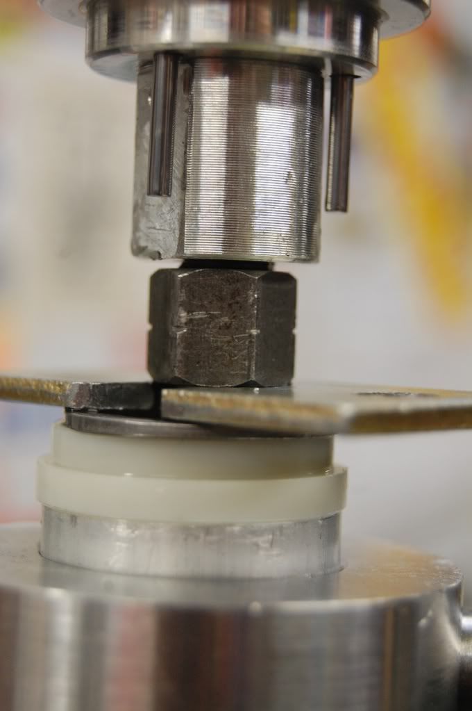
Fig. 9e:
With the rebound adjuster in the "in" position (i.e., where the adjuster should be closed) and the needle seated against its seat (i.e., fully closed rebound adjuster), you should see some air between the top nut and lock nut
When you have this sorted, I recommend you lightly lock the top nut in place with the lock nut, screw down the top nut in the fork leg, and do the extended / compressed routine again, taking down the dimensions. Presumably, the forks should bottom first, which in that case will now mean that the lower fork legs will bottom out against the bottom of the fork top nut.
Anyway, compare the fork stroke with the bare cartridge stroke; as long as the cartridge stroke is greater than the fork stroke, you are safe.
If not, go back, find the reason, compensate and proceed. Quickly said, but quite a lot of work, really.
Step 10: Fork re-assembly.
Next, screw off the top nut again, pour in some fork oil, either Öhlins R&T fork oil, or 5W fork oil of any known brand, and start working the cartridge up and down to get oil into the cartridge. Using a hose with a couple of holes in it will help you catch the cartridge rod down in the fork leg, and keep the oil under slightly better control. There will be oil most everywhere anyway when you are finished, but in this case less is better.
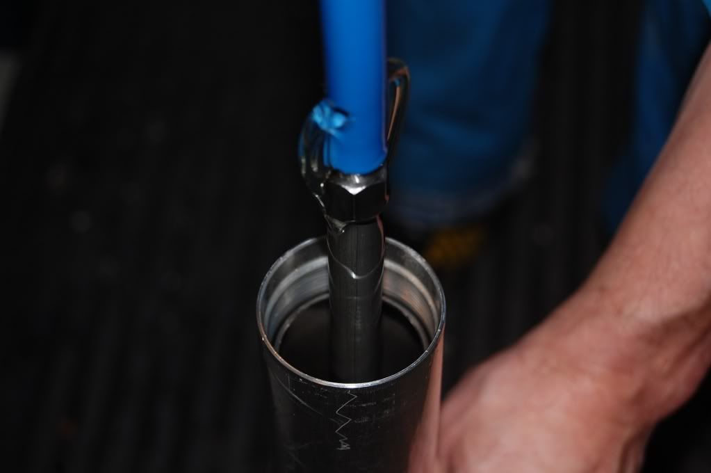
Fig. 10a:
Work slowly, or you´ll have oil all over the place ....
In the end, you´ll probably have oil all over the place anyway, but trying to be neat helps.
If the oil will not enter the cartridge, you have probably put the shim stack on the compression stack holder up-side-down (been there, done that ...). Pour out the oil, disassemble the cartridge from the fork, dissasemble the compression stack and correct. Have fun.
Pour in more oil, work the cartridge rod, and start measuring oil level. I usually start at 120 mm from the fork tube top with the fork fully compressed and no springs etc.; you might have other preferences. Keep it reasonable, a few mm this way or that might matter to Casey Stoner, but certainly not for me and probably not for you, but it´s your choice. If you decide on less air, make sure your forks will not lock due to oil overfill.
When the oil level is done, drop in the spring, spacer and associated hardware, and lock the spring under the lock nut with the grooved spacer described before.
Assemble the top nut as desribed in section 9, but after you´ve bottomed out the rebound needle, tighten the lock nut gently against the top nut, back off the adjuster a couple of clicks to protect the rebound needle, and tighten the lock nut against the top nut.
Remove the grooved spacer, make sure the spring spacer etc. are correctly positioned, and screw down the top nut in the top fork leg.
If you like, you could now do a "bump test": Screw both adjusters all the way out, and heave on the fork. It should pretty much pogo in and out with little resistance. Close the compression adjuster at the bottom of the leg and do the same; there should be a marked increase in resistance to compressing the forks. Now close the rebound, the return stroke should be real slow.
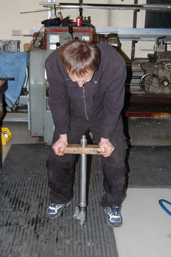
Fig. 10b:Bump test.
If you make a handle like his one, you can test various settings on your stock forks, and feel for any difference in compression or rebound damping.
On a standard fork, with the rebound damping even only slightly open, you will not feel very much difference at all in resistance when compressing the fork, no matter what the compression adjuster is set at.
Then do the same after you have modified your forks, and notice the difference: No matter where the rebound adjuster is set, there will be a noticeable difference in compression resistance with different settings of the compression adjuster.
Put the fork tubes back in the triples, tighten the lower clamp bolts to 15 Nm, tighten the top nut, and last tighten top triple to 15 Nm.
With everything in place, you can test the damping: Spring preload fully out, compression damping fully out, rebound adjuster fully out. Pull the brake lever and push down as hard as you can on the forks and let go. On rebound, the forks should lightly top out and sink back a little bit. Screw down the adjusters one or two clicks at the time until this happens. This is a good starting setting for the rebound damping.
Then set the compression adjusters 10 or so clicks out, put a tie-wrap around one of the forks legs (I prefer the right leg for convenience with the bike on the side stand), and push it up against the dust seal.You use this to evaluate spring preload and compression damping settings later after you have ridden the bike.
Set the sag to some sensible value, don your riding gear and take a ride, enjoying your immensely improved front suspension. Play with the adjusters until you think it feels right when going over bumps, braking (tie-wrap!) or whatever riding condition you think is important.
I always approach suspension settings from the soft side on all adjusters, working up to what I feel is right. This will take some time, but is well worth the effort; this whole modification is wasted if you don´t take the hassle to get the settings well sorted for whatever riding you do.
This might sound like a lot of work, and that´s because it is. However, if you plan on taking your forks apart for any reason, like a seal change, it´s not really that much more work. If you plan on doing a re-valve job anyway, only the manufacture of the alu rod is extra. You will have much improved suspension, and effective adjusters.
Just putting in a Racetech Gold Valve will not help (been there, done that ...), you have to do the modification to the rebound damping circuit to get an improvement.
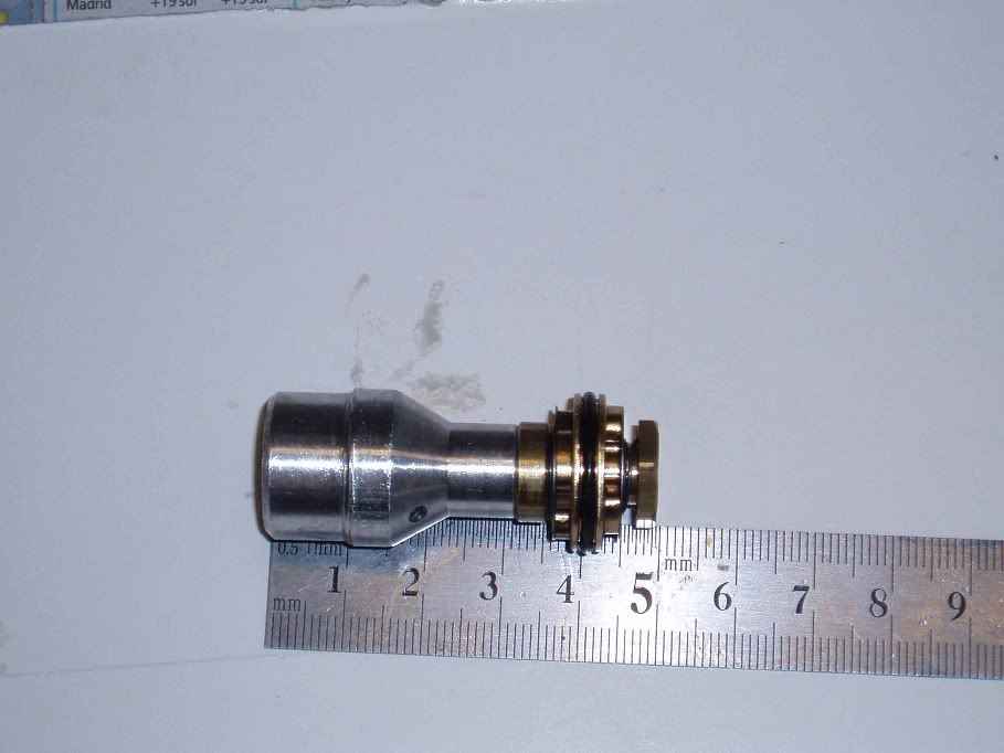
Fig. 10c:
Racetech Gold Valve.Not much change, but it was before I knew ...
You can also revel in the fact that you now have made a moderately expensive performance conversion that actually works but is invisible, as opposed to a lot of carbon fibre and such which is moderately to very expensive, very visible but makes no performance difference whatsoever :-) Well, in most cases anyway.
There is also the risk this mod will incur further cost; when you realize how nice good suspension is, you´ll probably want an Öhlins shock absorber as well pretty soon!
Tools needed:
• 6 mm allen key or socket for the triple clamp bolts;
• 22 mm socket for the spring preload;
• 32 mm wrench for the top nut;
• Spring compressor tool to compress the spring; not essential but very helpful;
• Slotted washer to keep the spring down;
• 14 mm and 17 mm wrench for the top nut and the lock nut;
• 19 mm socket with small outside diameter for the bottom plug
• Impact driver, also for the bottom plug,
• Piece of hose to help fishing up the cartridge rod when the spring, spring preload tube tec. are in place is very handy.
Disclaimer.
The modification outlined here is not the easiest and should not be attempted if you do not have the necessary skills and tools. I can´t say I had either when I started taking my forks apart, but in case of a screw-up I´d had no-one to blame but myself.
This how-to is written with the best intentions. Based on my own experiences and mistakes, it reflects the best of my knowledge, and I´ve tried to anticipate any problems you might encounter along the way accordingly. "Anticipate" in this case pretty much beeing an eufemism for "experiencing", actually, when I come to think about it.
However, I don´t expect it to be foolproof (you know how ingenious they can be ...), and you have to use your own judgement. If you do not feel up to the job, contact a reputable bike shop to do the job. If you do it yourself, you do it on your own responsibility, and if you screw up, it´s also on your own responsibility.
I also have to mention I have not actually ridden a bike with a fork modified as per this description. I have, however, ridden bikes with similar K-Tech mods, only using slightly different parts, and I have two bikes (OK, one and a half) with the first version mod using parts produced locally and Öhlins shim kits. They have all worked very well. No guarantee, sure, but an indication, I believe. Also, the bump test indicated the same result as previous modifications; at least a further indication.
Parts.
The K-tech parts used here are bits and pieces for various applications, the all-important rebound stack holder I think is for a "CR85/150 MX bike". I don´t know if that says something about Ducatis view of us Monster riders, sending suspension of this grade our way, but that´s what it is.
The parts needed are now available as a kit from K-Tech with the part number 20SSK-INT-SHO-13. Right now it contains the complete rebound stack with needle and spring, the complete compression stack with suitable, hollow M6 bolt. This means you have to use the stock compression stack holder.
Later, it will probably contain the the compression stack holder as well, so the kit will then be: rebound shim stack complete as a set on its holder with adjuster needle, and compression shim stack complete mounted on a new compression stack holder.
Edit: As far as I know, the kit does NOT include the compression valve holder.You will then just have to:
• Dissasemble the cartridge;
• Throw out the compression stack with holder and substitute for the new part;
• Take out the stock rebound piston as outlined in section 4;
• Replace with the new rebound stack assy, also in in section 4;
• Manufacture a new control rod as per section 9;
• Assemble the whole caboodle as per section 6, 7, and 10.
Unfortunately, Showa has several different combinations of fork leg, cartridge, and cartridge rod lengths out there. Therefore complete kits with rods and everything cannot be supplied as a default solution. Some probably could already now; you´d have to check with K-Tech.
As the database grows, I´m sure more and more models will be added to a list of complete kits.
Presumably, you could also order complete kits from K-tech by taking your forks apart, take out the cartridge rod, measure from the top down to the rebound piston flange and inform K-tec0 If you do so, be careful to also state bike model and model year so that the database can be made more and more complete with time.
I´m sure, they can also do the whole mod for you if you send them your cartridges. This might be more or less practicable depending on where you live. Contact K-Tech at
www.k-tech.uk.com for further details on parts and partners.
For those of you living in the US, there is a US disributor:
Orient Express
28 Grand Boulvard North
Brentwood
New York
11717
+1(6312) 319 552
skip@orientexpress.comLegal aspects and disclaimer.
Since we are very obviously dealing with safety-related parts and modifications here, and with the sue-for-money-if-you-can-or-even-if-you-really-couldn´t mentality rampant, I´m not sure if you can order the K-Tech parts yourself, or if you have to order them thru a dealer / retailer, or if you have to get the job done by a K-tech autorized bike shop. Check for a K-tech dealer close to you, and start the discussion with them.
I´m sure there are aspects of this job I have not thought about. If you set out to do this modification, you do it on your own responsibility and you have to use your own judgement and experience to make sure the job is done properly.
That said, if done properly I´m sure you will be very happy with the results.

